- 您现在的位置:买卖IC网 > Sheet目录3875 > DSPIC30F3014T-20I/ML (Microchip Technology)IC DSPIC MCU/DSP 24K 44QFN
2010 Microchip Technology Inc.
DS70102K-page 55
dsPIC30F Flash Programming Specification
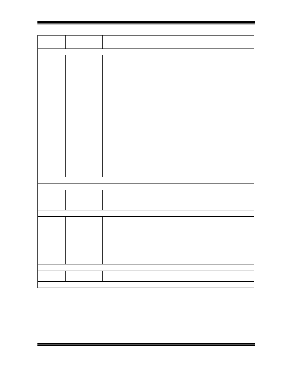
Step 8: Set the read pointer (W6) and load the (next four write) latches.
0000
EB0300
000000
BB0BB6
000000
BBDBB6
000000
BBEBB6
000000
BB1BB6
000000
BB0BB6
000000
BBDBB6
000000
BBEBB6
000000
BB1BB6
000000
CLR
W6
NOP
TBLWTL
[W6++], [W7]
NOP
TBLWTH.B
[W6++], [W7++]
NOP
TBLWTH.B
[W6++], [++W7]
NOP
TBLWTL
[W6++], [W7++]
NOP
TBLWTL
[W6++], [W7]
NOP
TBLWTH.B
[W6++], [W7++]
NOP
TBLWTH.B
[W6++], [++W7]
NOP
TBLWTL
[W6++], [W7++]
NOP
Step 9: Repeat Steps 7-8 eight times to load the write latches for the 32 instructions.
Step 10: Unlock the NVMCON for programming.
0000
200558
883B38
200AA9
883B39
MOV
#0x55, W8
MOV
W8, NVMKEY
MOV
#0xAA, W9
MOV
W9, NVMKEY
Step 11: Initiate the programming cycle.
0000
—
0000
A8E761
000000
—
000000
A9E761
000000
BSET NVMCON, #15
NOP
Externally time ‘P12a’ ms (see Section 13.0 “AC/DC Characteristics and
NOP
BCLR NVMCON, #15
NOP
Step 12: Reset the device internal PC.
0000
040100
000000
GOTO 0x100
NOP
Step 13: Repeat Steps 7-12 until all 23 rows of executive memory are programmed.
TABLE 12-1:
PROGRAMMING THE PROGRAMMING EXECUTIVE (CONTINUED)
Command
(Binary)
Data
(Hexadecimal)
Description
发布紧急采购,3分钟左右您将得到回复。
相关PDF资料
PIC16LF819T-I/MLTSL
IC PIC MCU FLASH 2KX14 28QFN
PIC16LF819T-I/SOTSL
IC PIC MCU FLASH 2KX14 18SOIC
PIC18LF8410T-I/PT
IC PIC MCU FLASH 8KX16 80TQFP
PIC18F2410T-I/ML
IC PIC MCU FLASH 8KX16 28QFN
PIC18F2331T-E/SOG
IC PIC MCU FLASH 4KX16 28SOIC
PIC18F4331T-I/ML
IC MCU FLASH 4KX16 44QFN
PIC16F690-I/ML
IC PIC MCU FLASH 4KX14 20QFN
PIC16C56A-04I/P
IC MCU OTP 1KX12 18DIP
相关代理商/技术参数
DSPIC30F3014T-20I/PT
功能描述:IC DSPIC MCU/DSP 24K 44TQFP RoHS:否 类别:集成电路 (IC) >> 嵌入式 - 微控制器, 系列:dsPIC™ 30F 产品培训模块:XLP Deep Sleep Mode
8-bit PIC® Microcontroller Portfolio 标准包装:22 系列:PIC® XLP™ 18F 核心处理器:PIC 芯体尺寸:8-位 速度:48MHz 连通性:I²C,SPI,UART/USART,USB 外围设备:欠压检测/复位,POR,PWM,WDT 输入/输出数:14 程序存储器容量:8KB(4K x 16) 程序存储器类型:闪存 EEPROM 大小:256 x 8 RAM 容量:512 x 8 电压 - 电源 (Vcc/Vdd):1.8 V ~ 5.5 V 数据转换器:A/D 11x10b 振荡器型:内部 工作温度:-40°C ~ 85°C 封装/外壳:20-DIP(0.300",7.62mm) 包装:管件 产品目录页面:642 (CN2011-ZH PDF) 配用:DV164126-ND - KIT DEVELOPMENT USB W/PICKIT 2DM164127-ND - KIT DEVELOPMENT USB 18F14/13K50AC164112-ND - VOLTAGE LIMITER MPLAB ICD2 VPP
dsPIC30F3014T-30I/ML
功能描述:数字信号处理器和控制器 - DSP, DSC 44LD 30MIPS 24 KB RoHS:否 制造商:Microchip Technology 核心:dsPIC 数据总线宽度:16 bit 程序存储器大小:16 KB 数据 RAM 大小:2 KB 最大时钟频率:40 MHz 可编程输入/输出端数量:35 定时器数量:3 设备每秒兆指令数:50 MIPs 工作电源电压:3.3 V 最大工作温度:+ 85 C 封装 / 箱体:TQFP-44 安装风格:SMD/SMT
dsPIC30F3014T-30I/PT
功能描述:数字信号处理器和控制器 - DSP, DSC 30MIPS 24 KB RoHS:否 制造商:Microchip Technology 核心:dsPIC 数据总线宽度:16 bit 程序存储器大小:16 KB 数据 RAM 大小:2 KB 最大时钟频率:40 MHz 可编程输入/输出端数量:35 定时器数量:3 设备每秒兆指令数:50 MIPs 工作电源电压:3.3 V 最大工作温度:+ 85 C 封装 / 箱体:TQFP-44 安装风格:SMD/SMT
DSPIC30F4011-20E/ML
功能描述:数字信号处理器和控制器 - DSP, DSC 16 Bit MCU/DSP 44LD 20M 48KB FL RoHS:否 制造商:Microchip Technology 核心:dsPIC 数据总线宽度:16 bit 程序存储器大小:16 KB 数据 RAM 大小:2 KB 最大时钟频率:40 MHz 可编程输入/输出端数量:35 定时器数量:3 设备每秒兆指令数:50 MIPs 工作电源电压:3.3 V 最大工作温度:+ 85 C 封装 / 箱体:TQFP-44 安装风格:SMD/SMT
DSPIC30F4011-20E/P
功能描述:数字信号处理器和控制器 - DSP, DSC 16 Bit MCU/DSP 40LD 20M 48KB FL RoHS:否 制造商:Microchip Technology 核心:dsPIC 数据总线宽度:16 bit 程序存储器大小:16 KB 数据 RAM 大小:2 KB 最大时钟频率:40 MHz 可编程输入/输出端数量:35 定时器数量:3 设备每秒兆指令数:50 MIPs 工作电源电压:3.3 V 最大工作温度:+ 85 C 封装 / 箱体:TQFP-44 安装风格:SMD/SMT
DSPIC30F4011-20E/PT
功能描述:数字信号处理器和控制器 - DSP, DSC 16 Bit MCU/DSP 20M 48KB FL RoHS:否 制造商:Microchip Technology 核心:dsPIC 数据总线宽度:16 bit 程序存储器大小:16 KB 数据 RAM 大小:2 KB 最大时钟频率:40 MHz 可编程输入/输出端数量:35 定时器数量:3 设备每秒兆指令数:50 MIPs 工作电源电压:3.3 V 最大工作温度:+ 85 C 封装 / 箱体:TQFP-44 安装风格:SMD/SMT
DSPIC30F4011-20I/ML
功能描述:数字信号处理器和控制器 - DSP, DSC 16 Bit MCU/DSP 44LD 20M 48KB FL RoHS:否 制造商:Microchip Technology 核心:dsPIC 数据总线宽度:16 bit 程序存储器大小:16 KB 数据 RAM 大小:2 KB 最大时钟频率:40 MHz 可编程输入/输出端数量:35 定时器数量:3 设备每秒兆指令数:50 MIPs 工作电源电压:3.3 V 最大工作温度:+ 85 C 封装 / 箱体:TQFP-44 安装风格:SMD/SMT
DSPIC30F4011-20I/ML
制造商:Microchip Technology Inc 功能描述:16- Bit Digital Signal Controller Memory